|
|
Home  support tips programming_MCP250xx support tips programming_MCP250xx
MCP250xx Programming
Programming the Microchip MCP250xx series ICs using a PICKit II programmer

The Microchip MCP250xx ICs are CAN Bus expanders.
- MCP25020 - No A/D
- MCP25025 - No A/D, 1-wire CAN
- MCP25050 - With A/D
- MCP25055 - With A/D, 1-wire CAN
To program them, instead of getting the development kit ($ 165), you can use free software and an inexpensive ($ 35) PICkit II programmer (which you may already have).
Programming these chips is not a straightforward process.
Plus, there are a few things to watch out for (the Microchip software is buggy).
This page gives you some tips to get you up to speed more rapidly.
- Get a PicKit II programmer
Do not get the PICkit III programmer. However, if you absolutely must use a PICkit III, see below for special instructions.
- Get a bunch of MCP250xx chips, DIP version (they are One-Time-Programmable, so every revision means using a new chip)
- Put a 14-pin DIP IC socket on your target
- If the target uses a SMD chip, build an adapter with a DIP socket and 2 short pieces of 0.05" pitch ribbon cable, each; mount the xtal oscillator directly on the DIP socket, not on the PCB
- Put a 5-pin 0.1" socket on your target for ICSP (In Circuit Serial Programming)
- Make sure there are terminations on the CAN bus: there should be 2, one at each end, but for test purposes a single termination will work
- Install a MCP250xx DIP chip in your target
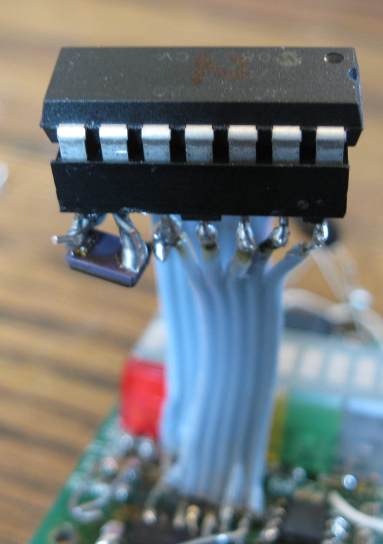
MCP2505x DIP adapter. Note the crystal mounted directly to the socket pins.
Use the MCP2505x Programmer application to configure the programming data. There are 2 types of data that you must configure at this point:
- Items that cannot be configured through the CAN bus, such as the settings for the CAN bus
- The default values of the registers (even though you will be able to change them later through the CAN bus):
- Either because you don't plan to change them later
- Or because you want to define the chip's behavior between power up and when you get around to change parameters through the CAN bus
- Enter the clock frequency. For example, enter 20000 for a 20 MHz crystal
- Click on the large button to select whether it's a MCP2502x (no A/D) or a MCP2505x (with an A/D)
MCP2505x Programmer window.
Note: selecting the type of oscillator will change the Configuration Word. However, the MCP250xx programmer doesn't save the Configuration Word to the HEX file
- CAN, assuming 500 kHz rate, 20 MHz crystal, standard ID
- Std ID / Ext ID: all "Std ID" (not pressed)
- Transmit:
- TXD0: leave at FF E3 (Raw ID = 7FF)
- TXD1: leave at FF E3 (Raw ID = 7FF)
- TXD2: leave at FF E3 (Raw ID = 7FF)
- Receive:
- RXM: leave at FF E3, StdID (Raw ID = 7FF)
- RXF0: take the ID you want to use to talk to the chip, multiply by 32 (20h), put the high byte in RXnSIDH, low byte in RXnSIDH. For example: 680h * 20h = D000h => D0h 00h
- RXF1: take the ID you want to use to write to registers, multiply by 32 (20h), put the high byte in RXnSIDH, low byte in RXnSIDH
- OPTREG2: set PUNRM to 1, leave the rest at 0s
- For 2 us bit time, 20 #TQ:
- BTLMODE: PS1 or IPT (not pressed)
- SAM: 3X (pressed)
- WAKFIL: OFF (not pressed)
- SJW: 1TQ
- Baud rate prescaler: 1 (all the way to the left)
- Propagation Segment: 3TQ
- Phase Segment 1: 8 TQ (all the way to the right)
- Phase Segment 2: 8 TQ (all the way to the right)
- Click "Close"
CAN screen.
Example, to get:
- No pull-up
- Pin 3 is a PWM output
- Pin 11 is an input
- 2.5 MHz square wave out of pin 10
- All other pins are outputs, preset a 0 at power-up
GPIO screen.
Note: selecting GP7 vs Reset for pin 11 will change the Configuration Word. However, the MCP250xx programmer doesn't save the Configuration Word to the HEX file
Example, to get:
- A PWM that goes from 0 to 100 % as we send data of 00h to FFh to the IC
- At power-up, defaults to full 100% PWM
- If the large button says "Off", click it to say "On"
- Click on the "PWM Period" label. A dialog opens
- Drag the slider almost all the way to the right, to FE (so that, when we set the duty cycle at FF, it exceeds FF and you get 100 %)
- Tip: if you can't get the desired number, because or low resolution of the slider, use the Arrow keys on your keyboard to nudge the value
- Click "Set" The dialog closes
- Click on the "PWM Duty Cycle" label. A dialog opens
- Drag the slider all the way to the right, to FF
- Click "Set" The dialog closes
- Save: File / Save Defaults
Use the PICKit II programmer.
- In the MCP250xx Programmer, save the data as HEX: File / Export HEX
- In the MCP250xx Programmer, note the "Config Word" (top left). The MCP250xx Programmer does not save the Configuration Word in the HEX file (we notified MicroChip of this bug), so you have 2 options:
- You can enter it manually (see later), or
- You can edit the HEX file: before the very last line (:00000001FF) insert a line, based on the value of the Configuration Word
| If the value of the Configuration Word is:
| Add this line before the least line in the HEX file
|
| 0
| :02400E000000B0
|
| 1
| :02400E000100AF
|
| 2
| :02400E000200AE
|
| 3
| :02400E000300AD
|
| 4
| :02400E000400AC
|
| 5
| :02400E000500AB
|
| 6
| :02400E000600AB
|
| 7
| :02400E000700A9
|
Example of modified HEX file
- Other than the 1st line, the MCP250xx Programmer does not generate the right checksums in the hex file
- The PICkit2 seems to ignore this as long as there are two hex digits in the checksum
- Occasionally the MCP250xx programmer produces a checksum that is missing a hex digit (see sample file) (we notified MicroChip of this bug)
- In that case, the PICkit2 sets all entries for that row to 34FF
- Edit the HEX file manually, to add a bogus digit (for example 0) to the end of the lines that are 1 hex digit short
- Make sure the target is not powered
- Connect the PICKit II programmer to the target and the USB port of your computer
- Open the PICKit II programmer application
- Select: "HEX only" (under Program Memory, middle left) If you don't do this, Windows will detect an unhandled exception (we notified MicroChip of this bug)
- Select: Device family / MCP250xx
- Select: Device / whichever part you're using
- To check the connection to the target, click "Read"; note that every word should be 34FFh (if it's 0000h, it's not connected properly)
- Select: File / Import Hex (Ctrl-I); Open the HEX file you saved earlier
- If you haven't edited the HEX file to include the configuration word:
- The application will complain that the configuration was not specified
- Click on "Configuration" (top right); a dialog opens
- Manually enter the configuration that you noted from the MCP250xx Programmer application (click a bit to toggle it)
- Click "Save"; the dialog closes
- Double check everything, because you get only one chance with these OTP (One-Time-Programmable) parts
- Click "Write"
- Note that the verify is succesful
PICkit II screen set up for the MCP25020 chip
- To control the GPIO (port):
- Place a 3-byte message on the CAN bus, at the address you programmed in RxF1 (680h in the example above)
- Byte 0: address: 1Eh to address the GPIO
- Byte 1: mask: determines which lines are affected
- 01h for just GPIO0
- 02h for just GPIO1
- 03h for just GPIO0 and GPIO1
- 04h for just GPIO2
- ... etc
- FFh for all lines
- Byte 2: data: to control the state of the affected lines
- 00h to clear all the affected lines
- 01h to set just GPIO0 (if the mask allows it) and clear the rest of the affected lines
- 02h to set just GPIO1 (if the mask allows it) and clear the rest of the affected lines
- 03h to set just GPIO0 and GPIO1 (if the mask allows it) and clear the rest of the affected lines
- ... etc
- FFh to set all the affected lines
- For example:
- To control just one line, for example GPIO2:
- The mask (byte 2 of the data) is 04h so that only GPIO2 is affected
- To set just GPIO2: 1Eh 04h 04h, or 1Eh 04h FFh, or 1Eh 04h 0Fh... the 3rd byte can be anything, as long as its bit 2 is set
- To clear just GPIO2: 1Eh 04h 00h, or 1Eh 04h F0h... the 3rd byte can be anything, as long as its bit 2 is clear
- To control 2 lines, for example GPIO2 and GPIO7:
- To set just those 2 lines: 1Eh 84h 84h, or 1Eh 84h FFh, or 1Eh 04h 8Fh... the 3rd byte can be anything, as long as its bits 7 and 2 are set
- To clear just those 2 lines: 1Eh 84h 00h, or 1Eh 84h F0h... the 3rd byte can be anything, as long as its bits 7 and 2 are clear
- To control all the lines:
- To set all the lines: 1Eh FFh FFh
- To clear all the lines: 1Eh FFh 00h
- To set GPIO2 and clear all the other lines: 1Eh FFh 04h
- To clear GPIO2 and set all the other lines: 1Eh FFh F7h
The PICkit III programmer is crap.
However, we recognise that MicroChip is hiding the PICkit II and pushing the PICkit III. Also, you may only have access to a PICkit III.
If you wish to use a PICkit III, please follow these instructions from Lorenzo Lea from the 2WheelsPolito race team.
- Dowload the PICkit 3 Programmer App and Scripting Tool v3.10
- Open the dowloaded file and unzip the "Pickit3 Programmer Application Setup v3.10" file
- Run the setup.exe application to install the PICkit III utility
- Connect the PICkit III programmer to a USB port on your computer
- Launch the PICkit III utility, which you will find in the MicroChip folder
- The utility will show a message indicating that it is in the MPLAB mode
- Select the "Tools/Download PICkit Operating System" menu item; a file open dialog will open
- Navigate to the MicroChip folder and select the PK3OSV020005.hex file
- If all goes well, the utility will look like this; else, if the utility says tha the PICkit III is not found, select the "Tools/Check Communication" menu
- Select "Device Family / MCP250xx" menu item
- Use the "Device:" button to select the specific device you are using
- Select the "File / Import" menu item to upload the HEX file you want to program onto your device
- Click the "Configuration" link; a dialog will open
- Set your desired configuration, click the "Save" button
- Clik the "Write" button to write the device
To restore the PICkit III to MPLAB mode, select the "Tools / Revert to MPLAB mode" menu item, and click the OK button in the dialog that opens
. The programmer will automatically download the firmware required to operate with MPLAB.
- Connect a CAN Bus monitor on the CAN bus
- Power up the target
- Check that you see a single message from the MCP250xx (typically: ID=7FFh, length-0; no data)
- If not:
- Check the 5 V supply on the IC
- Check for a termination on the CAN bus
- Check for the CAN bus speed (e.g.: 500 kHz)
- Check that the oscillator on the MCP250xx is runnning
- Check that the outputs are active and have the preset levels
|
|
 Li-Ion BMS