 Li-Ion BMS
|
Home White Paper - Charger Control Effective ways to let the BMS control the charger 
The BMS must be able to control the charger to protect the battery pack and to enable balancing.
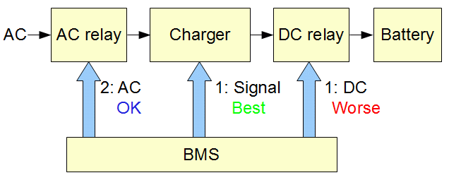
(The above is true of all chargers, even those that have a "Li-ion profile".) At the very least, the BMS must be able to turn the charger on and off (the ability to also control the current is optional). There are 3 ways for the BMS to turn the charger on and off:

1: Signal controlThere are two ways of doing so:
This is by far the best way, as it is simple, low cost, and in general is the most reliable. 2: Relay at the charger's AC input
A relay or contactor with contacts rated for AC is placed between the AC line and the charger's AC input.
Its coil is driven by the BMS.
This is the best solution for chargers that do not have provisions for low power control. However, this is disadvantageous if the charger includes a low voltage output (such as 12 V), which will become unavailable when the BMS turns off the charger. 3: Relay at the charger's DC outputA relay (or contactor) is placed between the charger's DC output and the battery. Its coil is driven by the BMS. This is the worse solution, as it has many disadvantages.
Primary reasons for placing a relay between the charger and the battery are:
Secondary reasons to isolate the charger from the battery include:
These should be weighted against the risk associated with placing a relay between the charger and the battery, and may be better solved by using a rectifier instead of a relay. Redundant methodsIf you don't trust the charger to shut off, and you want to add redundancy, then use the signal control method to turn the charger on and off during normal operation; in addition, use a relay between at the charger's AC input that is driven by a Fault output of the BMS, which is only triggered in case of extreme overvoltage of any cell. That way, the relay is never switched under load, except in case of emergency.
As an additional safety measure, make absolutely sure that the CV (Constant Voltage) setting of a CCCV charger is set for the maximum cell voltage times the number of cells in series.
For example, for 100 LiFePO4 cells in series, set the charger for 3.6 V x 100 = 360 V maximum.
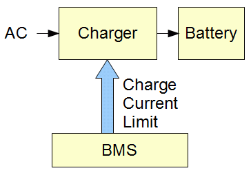
While not required, it may be desirable to be able to reduce the charger's output current:
In applications using large battery packs, typically the current from the charger is far less than the battery can handle. If so, usually there is no reason to reduce the charger current. For example, a 200 AH, 500 V pack may be charged with a 3 kW charger; that charger can only put out 6 A, which is a current of 0.03 C, far less than the 0.1 C termination current specified by the cell manufacturer, and low enough that it can be used to safely charge a Li-ion battery even below 0 °C. It's nice to be able to reduce the charger current down to the balancing current (say, 100 mA); that way, the charger is only turned off once, at the end of charging; also, the most charged cells are not subject to many cycles of being fully charged by the charger and then slightly discharged by balancing. However, those are minor issues. Therefore, again, usually there is no reason to reduce the charger current. Having said that, if it's easy for the BMS to reduce the charging current, one might as well implement it. 
There are two ways of doing so, using the CCL (Charge Current Limit):
The CCL can be used by itself, without on/off control, if the CCL is able to reduce the charger current down to zero. Davide Andrea, Elithion, 5/10/12 | ||
© 2008~2025 Davide Andrea. All rights reserved, except where noted by CC mark. Page published on May 10 2012. Graphic design by morninglori